This is an old revision of the document!
Introduction
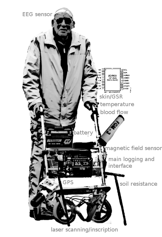
The psychogeophysics walker is a mobile, iconic platform for both urban and field exploration. The walker, designed around a disabled or aged person's walker or trolley, incorporates a range of sensors logging both the users biological/emotional states (EEG, skin resistance, skin temperature, blood flow and breathing patterns), and the local environment (magnetic field, high and low frequency signals, temperature, soil resistance where available) enabling a series of maps to be constructed of walked locations and correlations to be established between psyche and geophysical environment. The walker is optionally equipped with inscription device and laser scanner, enabling local fields to be either engraved on specific surfaces or such surfaces to be read back (the stone tape).
The psychogeophysics walker equally functions as an assemblage or catalogue of open hardware geophysical and bio-sensor designs and free softwares.
Hardware overview
With multiple serial connections to custom free software.
To resolve:
* How is all equipment mounted mechanically and connected?
1] Environment board
GPS (using LS20031 from http://www.tinkersoup.de/product_info.php?products_id=643), high and low frequency electromagnetics, local temperature, light, entropy and magnetic field gradient (FGM-3 from http://www.speakesensors.com/products.htm ).
Design notes:
- atmega32u4 for USB-serial connection
- powered by USB (see data sheet p255+)
- to test built in temperature reading of mega32u4
- FGM-3 board comms with env via SPI (for 3.3v ↔ 5v mismatch: see http://www.sparkfun.com/tutorials/65)
- GPS is also off-board. Parse GPS for N/E and time.
2] EEG
Following the openeeg project.
Refs:
http://www.1010.co.uk/org/openeeg.html
http://www.arduino.cc/cgi-bin/yabb2/YaBB.pl?num=1209080042/all
Software
Electrodes
To resolve:
- What are the electrodes?
Possibly use active electrodes:
http://openeeg.sourceforge.net/doc/hw/joe_ae/ NON! 2x batteries per electrode. but now we need to adapt own openEEG case!
http://uazu.net/eeg/ae.html : looks good for easy prototype
http://www.dcc.uchile.cl/~peortega/ae/
http://radek.superhost.pl/active_electrodes/
TODO: select design, order parts, build and test. Also resolve electrode placement (do we use 2 channels?), and cabling:
Maybe start with one channel (= 2 electrodes+DRL).
- How do we keep electrodes firmly in place and where do we place them?
From: http://arstechnica.com/civis/viewtopic.php?f=26&t=178288
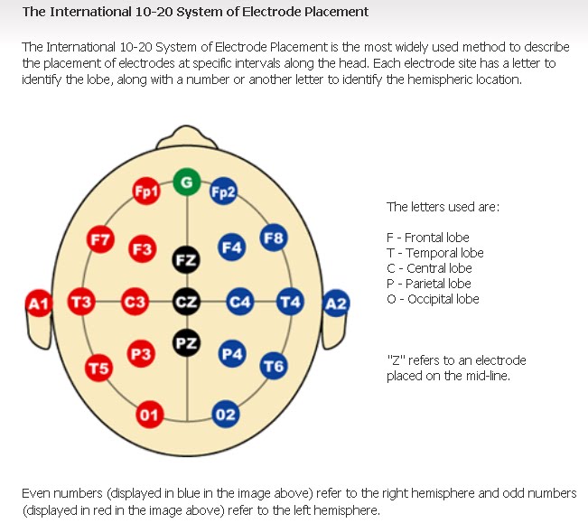
Common reference electrode positions are Cz, earlobes, mastoids, and the tip of nose.
If you only use one channel, you should connect your third (reference) electrode not to DRL but rather to VGND (this will however increase 50/60Hz noise). Or, if you do use DRL, connect CH2+ and CH2- to VGND or DRL.
Note difference between monopolar and bipolar setup:
By default, one always use differential amplifier (2 inputs: 1 non-inverter and 1 inverter input) which means that we are starting with a bipolar setup.
For instance, If you have 4 dif amplifier you will have 8 electrodes (e1,e2,e3,e4,e5,e6,e7,e8) over scalp but plotting 4 channels: 1st channel = e1-e2; 2nd channel = e3-e4, 3rd channel = e5-e6; 4th channel = e7-e8.
Now, if you want a monopolar set up with this example, you should “short circuiting” electrodes e2, e4, e6 and e8 together. So, you have a “new channel” called REF (REF=e2, e4, e6, e8 jointly). Now, you will have only four electrodes over scalp (e1, e3, e5 and e7), and the 5th electrodes will be REF (right mastoid for example). Your new recording will be monopolar with:
1st channel = e1-REF; 2nd channel = e3-REF, 3rd channel = e5-REF; 4th channel = e7-REF.
From: http://osdir.com/ml/science.openeeg.general/2006-09/msg00046.html
Bipolar: two electrodes on either side of the back of the head
Monopolar: one on the forehead and one on the vertex (top) of the head
Placement guide: www.focused-technology.com/downloads/eeghook1.pdf
Suggests either Mastoid or ear for reference, and Cz for other electrode with DRL on wristband
We could also combine plethy and DLR?
Ref for placement: http://www.bci2000.org/wiki/index.php/User_Tutorial:EEG_Measurement_Setup
3] Psych/body board
skin resistance (GSR), skin temperature, blood flow (plethysmograph), optional skin impedance (in fingers as perhaps replacement for plethysmography)
To resolve:
- How can we get a firm connection to fingers for both GSR and plethy (perhaps on ear)?
- Better solution for plethy than clothespeg on ear/finger?
- How to make fine tuning of GSR and plethy easier? AVR control of potentiometer!
Design notes:
- Atmega32u4 as above
Additionals
Earth resistance, scanning and inscription.
Skin environment feedback (a moving needle, electroshock).
Software notes
Python software (running on attached laptop) features:
- identify which of 3 USB serial ports is which
- collating 3x serial streams into one log (automatically saved at intervals).
- FFT of EEG data (see data format)
- some kind of user interface with error checking and live feedback/plotting
- at the same time needs to operate hands free and allow time for attachment/initialisation
- timestamp from GPS or laptop
- automatic generation of series of plots (selection)
- alignment mode for FGM-3
Questions to resolve:
- windowing toolkit/interface
- synchronisation of streams
- EEG data - how to log decently?
- general format for logfile with so much data (how many streams: 1) GPS 2) high 3) low frequency electromagnetics 4) local temperature 5) light 6) entropy 7) magnetic field gradient 8) EEG 9)skin resistance (GSR), 10) skin temperature 11) blood flow (plethysmograph) - so 10 or 11)


