This is an old revision of the document!
Ref: Walker
Resource
All diagrams and data in one place:
With 4.7k pullup on data line
With pin 1 as bottom left when we have square covered part in top right/battery top left.
TSL257 light amp
Pin mappings:
Mega: http://z8kxta.blu.livefilestore.com/y1pi3sgx69h4tAwlmL0n3B2nb2M_Wd3sAcJEhFR8E1NfI8N650Kucn-2sIGIWsHjW_TWRhTO-pXYlTBba3s6EoFRA/PIN MAPPING ARDUINO MEGA.jpg
atmega8: http://www.arduino.cc/en/Hacking/PinMapping
NMEA data: http://www.gpsinformation.org/dale/nmea.htm#nmea
GSV: $GPGSV,2,1,08,01,40,083,46,02,17,308,41,12,07,344,39,14,22,228,45*75 where 08 - 3rd digit is NUMBER OF SATS
To convert NMEA to decimal.
eg. 5205.5400, 00714.0191 = 52. +(5.4/60), 7. + (14.0191/60)
Proposed schedule
November
week 1- overall design, handling multiple streams(generating for tests:tap into GPS, miniscry, arduino), live logging and interface, FGM-3
week 2- EEG (active electrodes etch?), EEG processing, kicad designs, alignment of FGM-3 (what is support?)
week 3- software prototype more or less ready
December
- 1) env board + 4) psyche finished and tested
- complete software
- hardware questions and walker equipped
- tests
- soil resistance
- scanner
November 2011
9 Nov
Testing SPI communication for FGM-3 board and env board. Note: SS must be held high on the master or it reverts to slave: in the case of ATmega8 this is pin PB2.
10 Nov
Back to basics with the SPI. Testing one byte MASTER → SLAVE: all works well.
Different approach working now (for 1x FGM-3) - without interrupt on the slave. Just sends FreqCount constantly.
Slave code for ATmega8 and FGM-3:
- fgm_slave.c
#define F_CPU 12000000UL  // 12 MHz

#include <avr/interrupt.h>
#include <avr/io.h>
#include <stdio.h>
#include <inttypes.h>
#include <avr/delay.h>

/* frequency count 1st FGM */

unsigned long Freq;
volatile unsigned int FreqCount, count;

ISR(INT0_vect) {
  if ((PIND & (1<<2)) == 4) count++; //PD2 as INT0 PIN
}

ISR(TIMER1_COMPA_vect)
{
  FreqCount = count;
  count=0;
}


void WriteByteSPI(unsigned char byte)
{
  SPDR = byte;					//Load byte to Data register
  while(!(SPSR & (1<<SPIF))); 	// Wait for transmission complete
  }

void InitSPI(void)
{
  DDRD = 0x08;
  DDRB = (1<<PB4);	 // Set MISO as OUT
  SPCR = ( (1<<SPE)|(1<<SPR1) |(1<<SPR0)|(1<<CPHA));//|(1<<SPIE));	// Enable SPI, Slave, set clock rate fck/128
}

void delay(int ms){
  while(ms){
    _delay_ms(0.96);
    ms--;
  }
}

void main() {
  unsigned int count,y,z;
  unsigned char inbetween;
  unsigned int data;
  InitSPI();

  // set up timer
  fc_dur=8;
  OCR1A = 91; // let's say every second! now every 128th

  // TODO: enable interrupt on INT0 (and later on INT1)
  GICR |= _BV(INT0);
  MCUCR |= (1<<ISC01);
  MCUCR |= (1<<ISC00);

  TCCR1B |= (1 << WGM12);    // Mode 4, CTC on OCR1A
  TIMSK |= (1 << OCIE1A);     //Set interrupt on compare match
  TCCR1B |= (1 << CS12) | (1 << CS10);    // set prescaler to 1024 and starts the timer
  sei();

  while(1) {
    data=FreqCount;
    inbetween=(unsigned char)(data&0xff);
    WriteByteSPI(inbetween);
    inbetween=((unsigned int)(data)>>8)&0xff;
    WriteByteSPI(inbetween);
  }
}
Test master code for ATmega8 and FGM-3:
- fgm_slave.c
#define F_CPU 12000000UL  // 12 MHz

#include <avr/io.h>
#include <stdio.h>
#include <inttypes.h>
#include <avr/delay.h>

#define UART_BAUD_CALC(UART_BAUD_RATE,F_OSC) ((F_OSC)/((UART_BAUD_RATE)*16l)-1)

void InitSPI(void)
{
  DDRB = (1<<PB3)|(1<<PB5) | (1<<PB0) | (1<<PB2);	 // Set MOSI , SCK , SS /SS output=pin14 PB0
 SPCR = ( (1<<SPE)|(1<<MSTR) | (1<<SPR1) |(1<<SPR0))|(1<<CPHA);	// Enable SPI, Master, set clock rate fck/128
 PORTB|=0x04;
}

char ReadByteSPI(void)
{
  unsigned char addr;
  PORTB &= ~(1<<PB0); //low
  SPDR=0x01; // dummy data
  while(!(SPSR & (1<<SPIF)));
  addr=SPDR;
  _delay_us(1);
  PORTB |= (1<<PB0); // high
  return addr;
}

void delay(int ms){
	while(ms){
		_delay_ms(0.96);
		ms--;
	}
}

void serial_init(int baudrate){
  UBRRH = (uint8_t)(UART_BAUD_CALC(baudrate,F_CPU)>>8);
  UBRRL = (uint8_t)UART_BAUD_CALC(baudrate,F_CPU); /* set baud rate */
  UCSRB = (1<<RXEN) | (1<<TXEN); /* enable receiver and transmitter */
  UCSRC = (1<<URSEL) | (3<<UCSZ0);   /* asynchronous 8N1 */
}

static int uart_putchar(char c, FILE *stream);

static FILE mystdout = FDEV_SETUP_STREAM(uart_putchar, NULL,_FDEV_SETUP_WRITE);

static int uart_putchar(char c, FILE *stream)
{
  loop_until_bit_is_set(UCSRA, UDRE);
  UDR = c;
  return 0;
}

void main() {
  unsigned char d,dd;
  unsigned int count,x,y,z;
  unsigned long ttt, data;
  serial_init(9600);
  stdout = &mystdout;
  InitSPI();
  DDRD = 0x08;

  while(1) {

    PORTB &= ~(1<<PB0); //low
    SPDR=0x01;
    while(!(SPSR & (1<<SPIF)));
    ttt=(unsigned char)SPDR;
    _delay_us(100);
    SPDR=0x01;
    while(!(SPSR & (1<<SPIF)));
    ttt+=(unsigned int)(SPDR)<<8;
    PORTB |= (1<<PB0); // high
    printf("test: %ld\r\n",ttt);
    delay(100);
    PORTD ^=0x08; //flash
  }
}
DONE: test with 2nd FGM-3
TODO: test multiple serial streams with Python
Reference for FGM-3 frequency counting: http://scrying.svn.sourceforge.net/viewvc/scrying/freqcounttest.c?view=markup
11 Nov
- Assessing various active EEG electrode designs.
updated on main walker page
- Looking at multiple serial stream code:
Ref: http://eli.thegreenplace.net/2009/08/07/a-live-data-monitor-with-python-pyqt-and-pyserial/
- what is format of EEG?
from our own p2_parse.py (for eeg to OSC):
- p2_parse.py
import serial
import string
import sys
import time
import OSC

osc = OSC.OSCClient()

def send(message):
#    print message
    msg = OSC.OSCMessage("/xxxxx")
    msg.append(message)
    osc.sendto(msg,("localhost", 7777))

ser = serial.Serial('/dev/ttyUSB0', 57600, timeout=1)
try:
     # parse modeeg P2 format until user interrupts
     state = 1
     while 1:
         if state == 1:
             # find sync0 (0xa5)
             x = ord(ser.read())
             if x == 0xa5:
                 state = 2
         elif state == 2:
             # find sync1 (0x5a)
             x = ord(ser.read())
             if x == 0x5a:
                 state = 3
         elif state == 3:
             # read data
 #            print 'reading data'
             version = ord(ser.read())
             count = ord(ser.read())
             s = ser.read(12)
             # add high and low bytes for each channel
             data = [ord(s[i])*256+ord(s[i+1]) for i in range(0,len(s),2)]
             switches = ord(ser.read())
             send(data)
             state = 1
except KeyboardInterrupt, e:
     print 'closing serial port'
     ser.close()
TODO:
- multiple streams written to a file with timestamps
Decoding of GPS NMEA stream with time and location (also for N and E)
Ref for GPGGA:
http://www.gpsinformation.org/dale/nmea.htm
But parsing is done on microcontroller as per new skry - but now with date and N/S E/W.
- think on architecture
indicate start up, wait, identify ports, check sanity, attach threads, attach gui, feedback.
12 Nov
- Resolving voltage/power question for brds as some need 5v and 3.3v
21 Nov
Re-testing the underground observatory (walker related) after quick code check. Collect and analyse tommorrow.
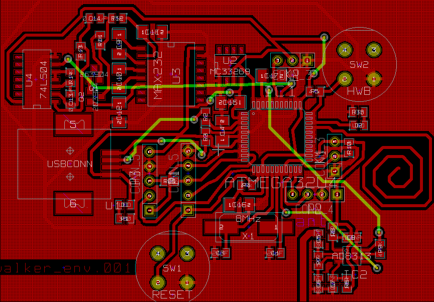
Environment and psyche PCB designs completed and ready for etching (by Martin Kuentz).
TODO:
- software - GPS parsing on mega8 for testbed (but we have only one serial port! arduino?)
- ———- split incoming serial (from mega8: fgm, low freq, “fake” ADC values)
- incoming:
1st serial: 1) GPS 2) high 3) low frequency electromagnetics 4) local temperature 5) light 6) entropy 7) magnetic field gradient
[or parse GPS on PC and have as one serial stream itself - make sure VCC=3.3v]
2nd: 1) EEG
3rd: 1)skin resistance (GSR), 2) skin temperature 3) blood flow (plethysmograph) 4) skin impedance
- ———- multiple threads for each serial stream
- ———- GUI (qt4) - fullscreen start, new windows, full automation, multiple plots, single key navigation
- EEG - active electrodes
- —– parsing and analysis
5933 tests:
Testing Analog Device AD5933 connected to finger/foil pads. Frequency for impedance testing of skin is 10 KHz (try other frequencies). Impedance drops off very rapidly with increasing sweat (I think).
LS20031 GPS:
With pin 1 as bottom left when we have square covered part in top right/battery top left.
Notes:
Working with bio-amp and wheatstone with live plotting:
wx_mpl_dynamic_graph.py codebase from http://eli.thegreenplace.net/2008/08/01/matplotlib-with-wxpython-guis/ is too slow/eats CPU (even when we drastically reduce update rate)
so we focus attention on plotting_data_monitor.py from http://eli.thegreenplace.net/2009/08/07/a-live-data-monitor-with-python-pyqt-and-pyserial/
roughly ported to GNU/Linux.
22 Nov
Notes:
- Some kind of needle feedback (attached to one of sensor inputs) and hand.
- curses interface (showing activity, plotting and logging)
- Break down into two applications: one for live attachment/logging and feedback and one (with menus) for plotting:
eg. for latter: select data streams, file name for input, for output, generate plot(s)
- Question of placement for impedance electrodes (and where to get these) rather than fingers: wrists, chest… also perhaps as replacing plethy and GSR
Refs:
http://docs.python.org/howto/curses.html
http://reza.net/wordpress/?cat=4
http://iris.elf.stuba.sk/JEEEC/data/pdf/2_109-1.pdf
23 Nov
Underground observatory:
Seems (again) to stop recording when buried.
Testing inside and outside of default setup.
INSIDE: 16.49 to 17.53 GMT. voltage start=8.92v end=8.83v lines recorded=80614+1778
OUTSIDE: 17.56 to GMT. voltage start=8.83v end=18.18 STOPPED lines recorded=7785 last temperature=11.1
Now testing outside without FGM-3:
19.05. 8.7v (lasted until approx 19.20)
notes:
Further FGM ref: http://www.reeve.com/FGMSensors.htm
Conclusion is that (cheap) alkaline batteries cannot provide enough current for FGM-3 and board. To switch to Lithium or NiMH.
Walker:
Constructing active electrodes following: http://uazu.net/eeg/ae.html
We need to attach our new DIN socket for active electrodes to +v and -v (aka. AGND). Following the schematic for openeeg at: http://openeeg.sourceforge.net/doc/modeeg/modEEGamp-v1.0.png
We could wire into C227.
24 Nov
Active electrode construction (see above):
wiring:
screen to VGND, and for each electrode: brown=V+, pink=signal, green=V-
from bottom of DIN going clockwise from back/wiring side: SIG1, SIG2, VGND, +5v, -5v(AGND)
4 December
TODO:
- test chest impedance (electrodes ordered)
- easy solution for GSR
- feedback for walker
- EEG/active electrode tests + parsing (headband?) - DONE
- mountings and order walker
- test-bed setup - DONE
- software - parsing/splitting, EEG, serial streams, threading and sync
- when brds arrive construct and test
Refamiliarise with EEG notes
How to test the new electrodes? Using eegmir and touching electrodes (we had -V and +V wrong way round and fixed by wiring brown of main cable to green of electrodes and vice versa)
Software which runs under Linux and which could be used or adapted for recording:
Our own p2_parse.py, eegmir, minicom with 57600 8N1 and logging
rec-modeeg in bwview:
use as in: ./rec-modeeg /dev/ttyUSB0 and then it writes to test.dat and opens bwview (we needed to change rec-modeeg to use mod0 protocol first)
neuroserver:
./nsd& then ./modeegdriver and can…
telnet localhost 8336 (commands: display, watch 0)
or use writeedf and readedf… testing (but what is readedf doing?)
… and interpretation:
bwview:
[above to give some idea of settings which are accessed with appropriate key eg. c for channel]
eg. ./bwview mod0/256 testfile (but doesn't work with minicom logged data, only with rec-modeeg test.dat)
Reference also: http://code.google.com/p/mindbridge/source/browse/trunk/?r=7#trunk%2Fnoodling
5 December
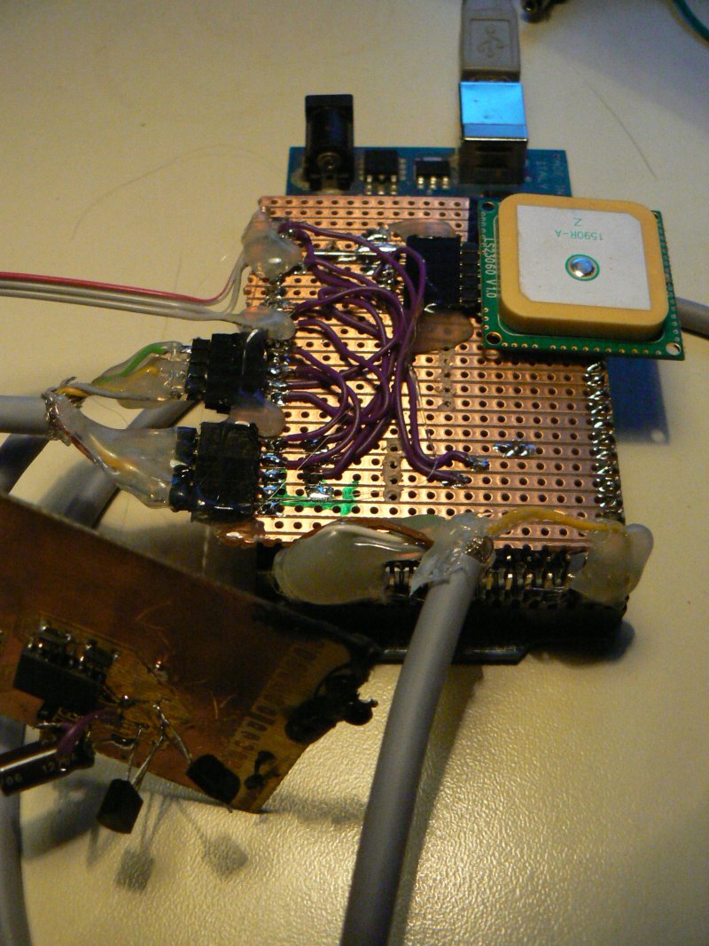
Testbed on arduino constructed using LS20031 GPS module (NMEA parsing based on: http://www.jarkman.co.uk/catalog/robots/gpsamin.htm)
Module outputs at 57,600 baud as default rather than 9600.
TODO:
- headband and further tests
- software - parsing/splitting, EEG, serial streams, threading and sync
Notes:
Experimenting with EEG/new headband setup as follows:
One active electrode on left forehead side, one close to ear (mastoid?) held in place with elastic band. DRL clipped onto finger (should try with wrist). Using eegmir to test with bar gain of 20.0.
Test with 10-20 EEG paste on DRL = no great improvement on 50 Hz noise!
Still question of how to deal with the EEG data: sample rate=256 Hz at 57600 baud. Thus all comms at 57600 to recognise eeg usb/serial port
TODO:
- how to integrate EEG, GSR – DRL (wristband?), finger connection, easy headband?
6 December
FGM-3:
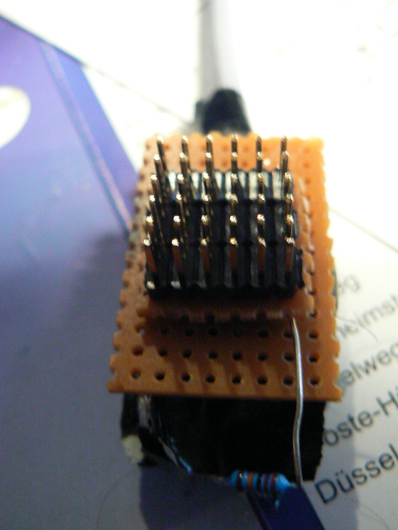
Building FGM-3 sub-board. Connection to Mega32u4 via. 5 pins left to right: 1-VCC, 2-GND, 3-SS, 4-SCK, 5-MISO
For FGM-3 connections on colour coded cable:
Colours: Green and yellow as FGM signals, brown=VCC, grey=GND. With flat side of connector to left of Mega8 brd and as follows: sig1, VCC, sig2, GND.
Decoupling: 22uF to GND from power, 10 ohm from 5v to power.
EEG:
Testing passive electrodes (silver chloride or silver chloride, with Ten20 conductive paste) against active. Also tuning electrode placement as follows:
+ on forehead, - on earlobe (clip we used to use for DRL) and DRL held in hand…
Passive electrodes more comfortable and seem to respond well in preliminary study (blinking). So we stick with scheme above but:
One question is whether GSR and/or impedance measurement will effect the EEG signal.
Reference for electrode placement: http://neurofeedbackprojects.blogspot.com/2009/12/clear-and-concise-information-on.html
Software:
Threading implemented for EEG and GPS/testbed data. Question is of cleaner format (buffering), feedback and how to integrate env and psyche data (perhaps in one thread).
7 December
Software:
Cleaned up EEG/testbed data logging, added file header and timestamps for env/GPS stream.
Need to test psyche/env (perhaps to cobble together two boards).
TODO:
- easy solution for GSR/imp/finger connection? kind of DONE
- and for feedback for walker? - as optional shock/needle feedback.
- backup if brds aren't arriving: use mega8 board and serial conv, borrow entropy board or construct new one
- FGM-3 fixingDONE, tests and alignment (MON+)
- test GSR and impedance on some kind of wristband (with foil or with studs)DONE
Other: re-test underground observatory with charged NiMH batteries.
Notes:
No great results with impedance and both medical EKG electrodes and home-made foil/elastic chest band. Foil bands on fingers (borrowed from GSR) as most successful so far.
To map out body attachments for the walker and how to integrate these with the frame:
EEG - scalp/forehead (+) by way of headband, earlobe (clip) (-) and wrist/finger(make a wristband) (DRL)
GSR - fingertips - perhaps devise clip mechanism for easy attach/re-attach, imagine also some kind of box into which fingers can be inserted on the walker handles.
IMP - fingertips, test other skin points?
As optionals - shock pulses, hand inscription.
Other integration options:
We measure resistance and impedance from copper or silvered handles (isolated from rest of frame) of the walker itself. (problems: variation in strength of grip, sweat).
Also to look into how walker can be more integrated with measurements; as antenna, as body/skin connection.
8 December
Commenced psyche.pde (home made arduino) and env.pde (for arduino mega)
Skin temperature:
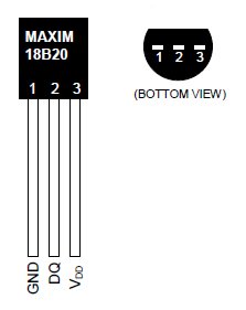
Examining skin temperature measurement using ds1820:
4.7k pull-up from data pin to +V.
Positioning: suggested on middle or index finger. First tests fix with gaffer tape. Needs to be more solid!
Code ref: http://www.arduino.cc/playground/Learning/OneWire (slow data acquisition)
FGM and connectivity from fgm-sub-board:
“On the Arduino Mega, this is 50 (MISO), 51 (MOSI), 52 (SCK), and 53 (SS).” Let's say SS on master/arduino mega is pin 2 for now.
So 5 pins from FGM-3 sub-board (construct cable) go to Arduino Mega from left to right (GND, 5V, pin2 (SS), pin52 (SCK) and pin50 (MISO).
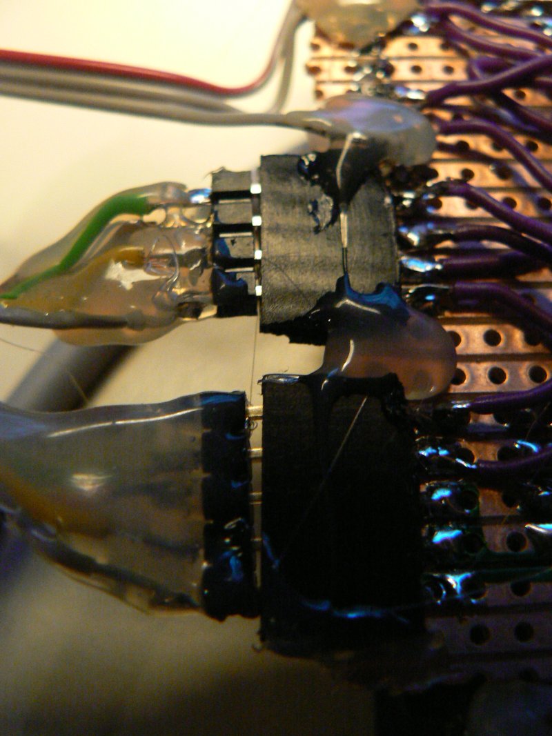
Cable in from FGM-3s is with green on the left (make connection strong with hotglue).
9 December
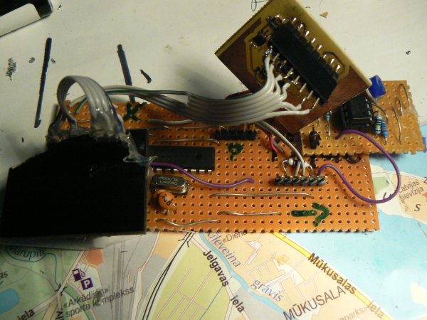
Finished rough_and_ready psyche board based on mega8 diy/arduino scheme. Connection to sensors (from left) as follows:
1-GND, 2-VCC, 3-4-skin/impedance, 5-datapin of DS18S20(temp),6-GSR signal
To think on: waterproofing of eg. FGM-3 structure - use plastic pipe (also pipe as way of standing FGM strcuture away from metal of the walker).
- where is placement of env sensors (eg. temp/light: in air, RF slightly away from main board, GPS in free sight but could be on board or close, FGM remote, entropy on brd). Leave final placement until we have walker.
- what we use for makeshift LF, HF sensing: old detektor brd (but bypass power reg) DONE
- armbands for GSR, impedance and DRL.
pain register:
Providing needle (bio-)feedback on chosen environmental measurements (eg. local magnetic field strength).
Tested with servo and serial connection to arduino. For walker could use with env board but need to choose which sensor to tie into for feedback.
More detail at: http://www.1010.co.uk/org/notes.html#69
12 December
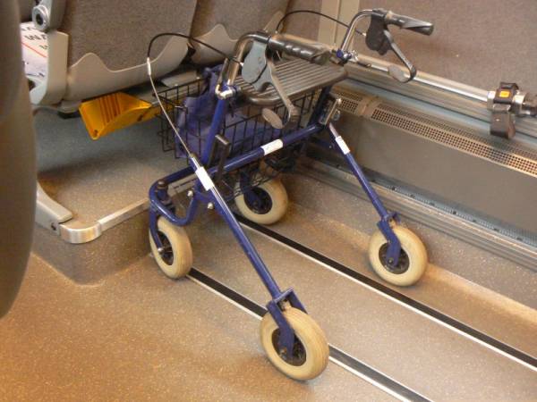
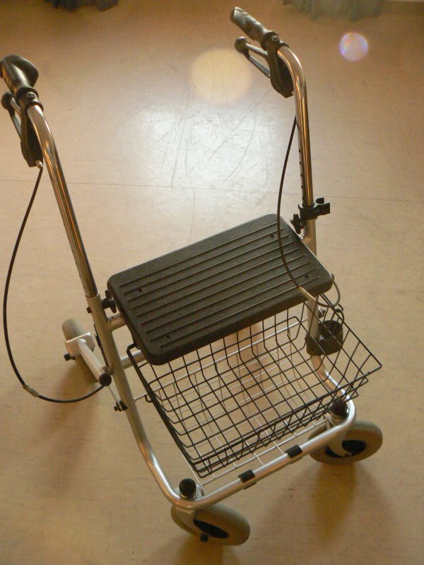
Arrival of the walker… ready for equipping as PgW.
TODO:
- alignment of FGM-3
- assemble env setup and test (also cabling) DONE
- tests and potential construction of wristbands for DRL, GSR and impedance. DONE
- attach all equipment and waterproofing (gaffer, containers, plastic pipes, bungies) TODO
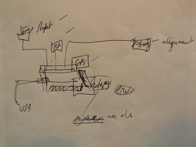
environment plan:
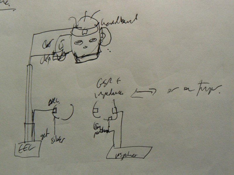
psyche plan:
13 December
Fixing RNG/entropy board - the capacitor from pin 2(V+) of MAX232 should go to VCC (5v) to generate +10v (pin 2) and -10V (pin 6).
14 December
Also added +- 10K resistors for incoming AD8313 signal.
Env board attachments:
- on main board both with green/brown on left (with sub left)
- on detector: brown/green on left and yellow/grey on right with coil top left
- FGM is connected with yellow at top to arduino
- on FGM board FGM cable is with green to left and cable to main env is with green to RIGHT!
Psych board:
Construct 6 wire interface from psyche to wristband with mounted connection also to fingers. DONE
again: left; 1-GND (GREEN), 2-VCC, 3-IMP1, 4-IMP2, 5 TEMP, 6 GSR
15 December
TODO:
- flashing/tests for env and psyche (+ test new format) DONE
- test testserial.py with 3 streams running DONE
- start on parsing data format (menu for selecting data file) and plotting app. DONE
- wooden construction, boxing up and all wiring DONE
- format for writing data from testserial.py for new plotter.py to parse DONE
16 December
Working on testing each stream and to see how to format all together. Now we also specify number of streams we want attached:
… as in python testserial.py 1 for one stream.
Fixing psyche.pde and env.pde (57600 baud as default, fixed slow GPS updating).
18 December
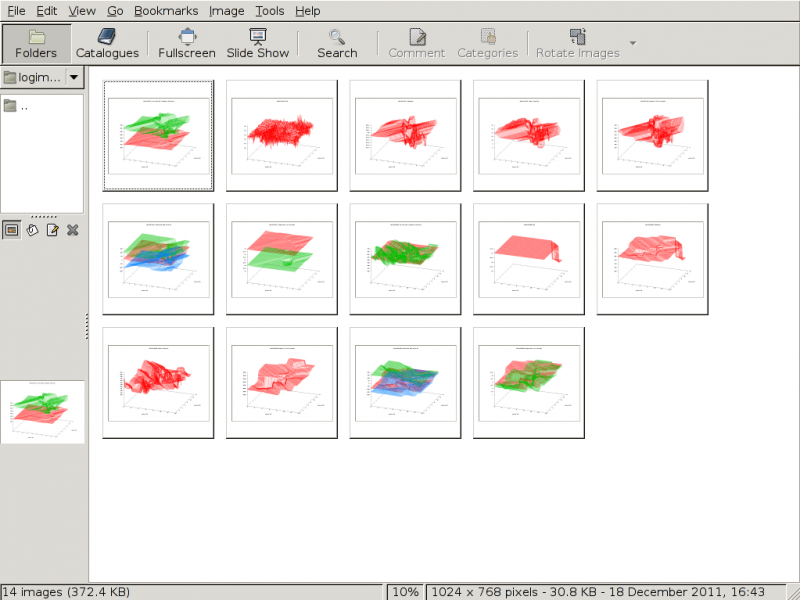
Plotter.py seems to be working fine - writes a series of plot images to directory logimages (under where we have software) and reads from menu. Plotter.py also writes intermediate file to timestampmod.log
testserial.py handles all streams and writes GPS + EEG data to timestamp.eeg.log
19 December
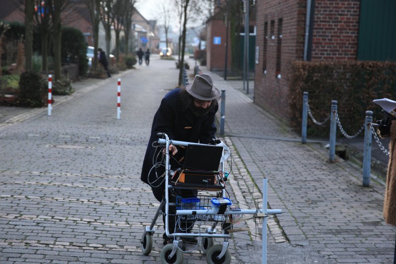
[Image: Stefan Demming]
Tested outside with no GPS fix. Testing inside (on table in front of window) and fix is sometimes very fast, sometimes slow. Testing now with cable detaching GPS from board…
FIXED: TX from Arduino was not connected
REF also for Locosys LS20031: http://www.laptopgpsworld.com/3701-diy-gps-module-using-locosys-ls20031
20 December
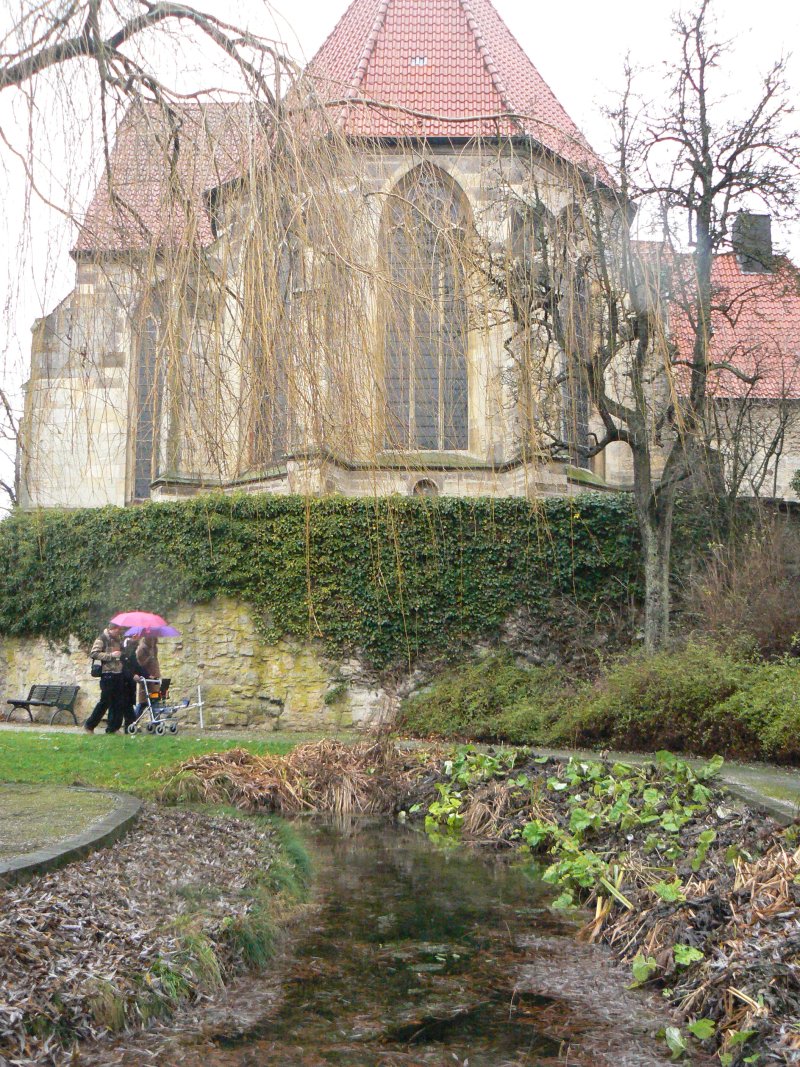
[Image: De Lane Bredvik]
Second outside test run results:
Problems:
- FGM disconnected accidently part way through walk
- incorrect EEG GPS tag: fixed in testserial.py TODO: test
- GPS location stuck half way through walk ????
- overwriting of queues: fixed perhaps by writing to queue in one go - TODO: test
21 December
Addressing problems:
- GPS stuck seems to be when we have no GPS signal but module still offers up co-ordinates. How to test for this (or change to different module)
- EEG GPS tag: fixed. TODO: re-test 3 streams
- queue overwrites: fixed under 1 hour tests (but one short stoppage for psyche board noted)
